

D.4.1 Electromotive Force (emf)
Electromagnetic Induction
•
As in topic 5, the phenomenon that states the force acts on the charge when an electric charge moves in the magnetic field.
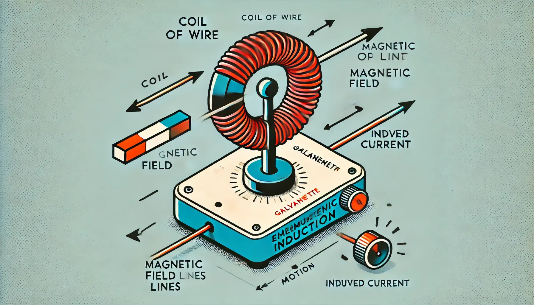
Solenoid Experiment
•
When moving a magnet in and out of the coil, an electrostatic current is generated through the solenoid.
•
Several rules of the phenomenon:
◦
Current appears when there is a relative motion of the magnet; if there is no motion, the current generated will be zero
◦
Current flows in the direction to oppose the motion of the magnet
◦
Clockwise flow at the end represents the south pole, and anti-clockwise flow represents the north pole

D.4.1-1 Direction of the magnetic force on the solenoid
•
The greater the speed of the magnet into the coil is, the more current is generated
Electromotive Force
•
When a conductor moves in the magnetic field, an electromotive force (emf) is induced.
•
Emf is dependent on:
◦
Speed of the wire
◦
Strength of the electromagnetic field
◦
Length of the wire in the magnetic field

D.4.1-2 Induced conductor in moving in the electromagnetic field
•
When the conductor is induced, free electrons inside the conductor move in order to oppose the motion.
•
Some observations of this experiment:
◦
The direction of the movement of the electron is called the electron flow, and the opposite direction is called the conventional flow.
◦
The potential difference can be measured between R and L
◦
The directions can be determined using Fleming’s left-hand rule in the next topic
•
The charge that moves around the complete circuit is called induced emf.
From this experiment, the forces on the electron are:
1.
Electrical force
2.
Magnetic force
•
Both forces are applied in equal and opposite directions along the conductor.
•
This leads to the equation of the potential difference between the two ends:
•
If there is no current flowing, the emf is equal to the potential difference:
D.4.2 Magnetic Flux, Faraday’s/ Lenz’s Law of Induction
Fleming’s Left-Hand Rule
As in the diagram below, with the direction of the force and magnetic field, we are able to predict the direction of the current.
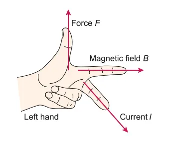
D.4.2-1 Fleming’s left-hand rule
Lenz’s Law
•
The direction of the induced current is such as to oppose the change that created the current.
Consequences of Lenz’s Law:
•
As following the conservation of energy, the current should be induced since there is no source of kinetic energy gain while moving the magnet into the coil faster
•
If there is no opposing force, current cannot flow inside the circuit, which means no electric energy is produced.
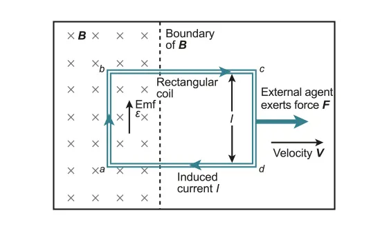
For Conductors Moving On a Rail:
•
The electromagnetic induction happens between the rolling rod and the rails
◦
Electrons flow from the rails through the rolling rod
•
Motor effect force is applied in the opposite direction to the motion to follow the conservation of energy and Newton’s first law of motion
•
The number of magnetic field lines inside the circuit will change, which will lead to the definition of flux below

D.4.2-2 Conducting rod rolling on rail within the magnetic field
Magnetic Flux Density
Since the term v refers to the speed of the rod, the term lv is equal to
considering the swapping area:
The equation of the emf can be rearranged for:
•
The induced emf is equal to the rate of cutting of flux in the area given.
•
Magnetic flux density is numerically equal to the magnetic field strength, B.
•
It is related to the number of field lines per unit area.
•
The strength depends on how much the magnetic field lines are separated.
•
Unit: Wb , tesla (T)
Magnetic Flux
•
The number of streamlines going through the sock.
•
It is a scalar quantity equal to the multiplication of the area and flux density that is normal to the area:
if the field lines are normal to the area)
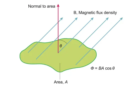
D.4.2-3 Definition of magnetic flux
•
Unit: Weber (Wb).
•
Change in flux over time taken for change.
•
A rate of change of flux of one Weber per second induces an emf of one volt across a conductor.
Magnetic Flux Linkage
•
Since the rod example above only considers the change in area in a single circuit, the quantity will change if the same situation applies to multiple coils.
•
Magnetic flux linkage: If there are N turns of wire in the coil, the magnetic flux linkage is:
•
Unit: Weber turns
•
‘Turns’ can be discarded since N is an integer without units.
•
Faraday’s Law
•
The induced emf in a circuit is equal to the rate of change of magnetic flux linkage through the circuit.
•
It can be expressed in an equation:
•
The negative sign is added to Lenz’s law.
•
This is because the electromotive force in the coil opposes the change in magnetic flux.
Changing Fields and Moving Coils
The change in magnetic flux density inside the circuit happens in several different cases:
•
Changing the area over time
◦
In this case, the total emf produced will change according to the emf equation above.
◦
If using multiple coils in the same case, the value of emf will increase as:
D.4.2-4 Coil moving out of the magnetic field
•
Referring to the definition of flux, the induced emf of the moving coil will be:
•
Changing the angle
•
over time
◦
In the particular example where rotating a coil at 180°, the magnetic flux density increases for the first 90° and decreases for the rest of the rotation.
◦
The sign will be opposite for each motion.
◦
The change in flux will be:
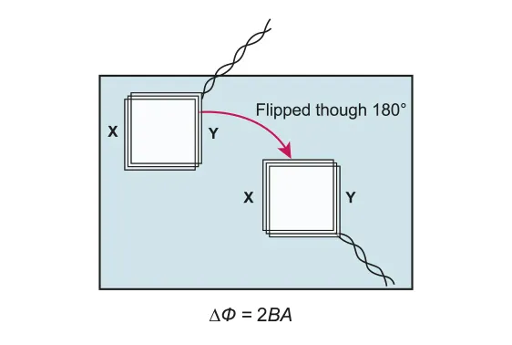
D.4.2-5 Coil rotating in 180° inside the magnetic field
•
The emf in this case will be equal to:
•
Changing magnetic flux density over time
◦
To determine the emf change in the circuit, change in magnetic flux can be found as:
•
Since the area is constant in this case, the change in magnetic flux density will depend on the change in flux and emf.
•
The equation of emf that may be used in this case is: