

A.2.1 Newton’s Laws
Force
•
Forces vectors that cause objects to accelerate
•
Objects that experience zero net force, move in a straight line at a constant velocity
•
Bigger forces accelerate objects faster
•
If the same force is applied to two objects of different masses, the object with larger mass will accelerate less than the object of smaller mass
•
Forces are vectors, so if more than one force acts on an object, the forces add up through vector addition.
•
The total sum of the vectors is a vector called the resultant force. The magnitude of the sum of all the force vectors is called net force.
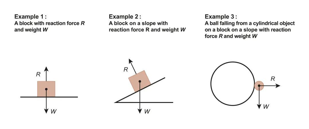
A.2.1-1 Example of normal reaction forces
•
Gravitational forces
◦
The force of attraction between any two bodies is directly proportional to the product of their masses and is inversely proportional to the square of the distance between them
•
Tension forces
◦
force transmitted through a rope, string or wire when pulled by forces acting from opposite side
•
Normal reaction forces
◦
force acting perpendicular to two surfaces in contact with each other
Newton 1st Law
•
An object in motion will remain in uniform motion and an object at rest will remain at rest unless acted upon by a net external force.
•
When no forces act on an object or the net force is zero (F=0, i.e. in equilibrium state), the object's velocity will not change
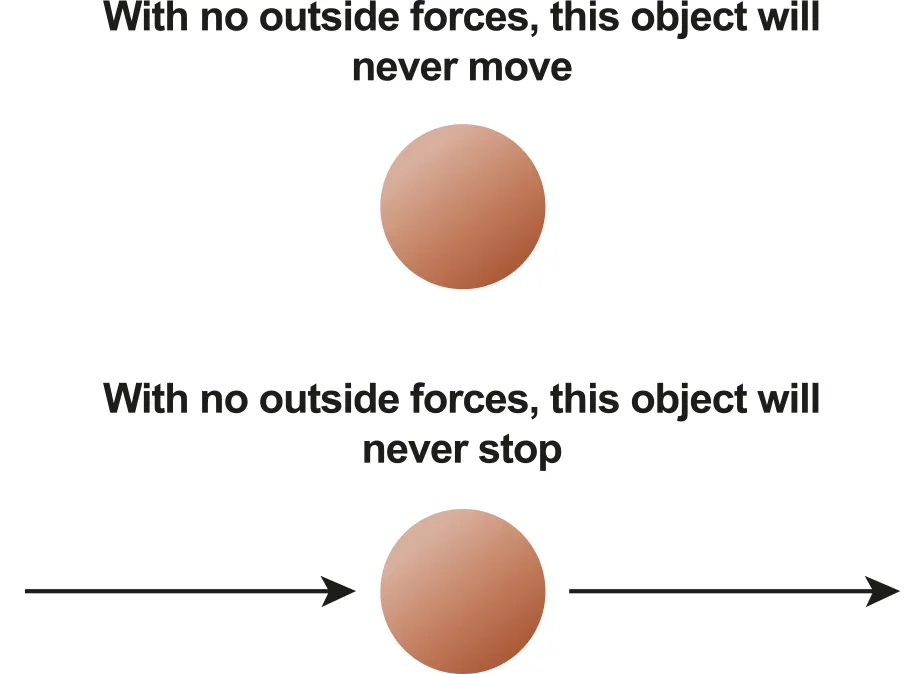
A.2.1-2 Diagram explaining the 1st law
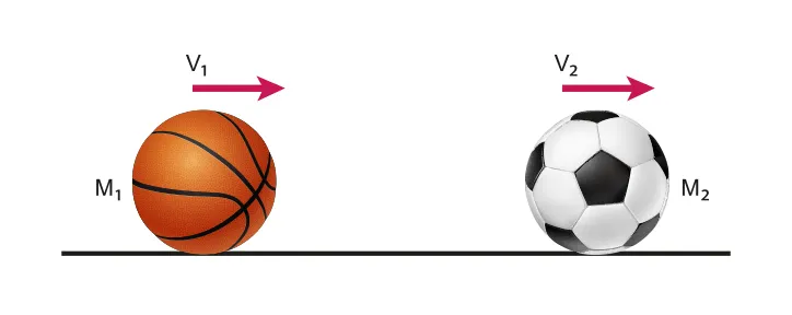
Newton 2nd Law
•
Newton’s second law states that the force required to accelerate an object is proportional to both the mass and acceleration
•
Where m is mass of the object(kg), a is the acceleration(m/s2 ) and F(N) is the resultant force
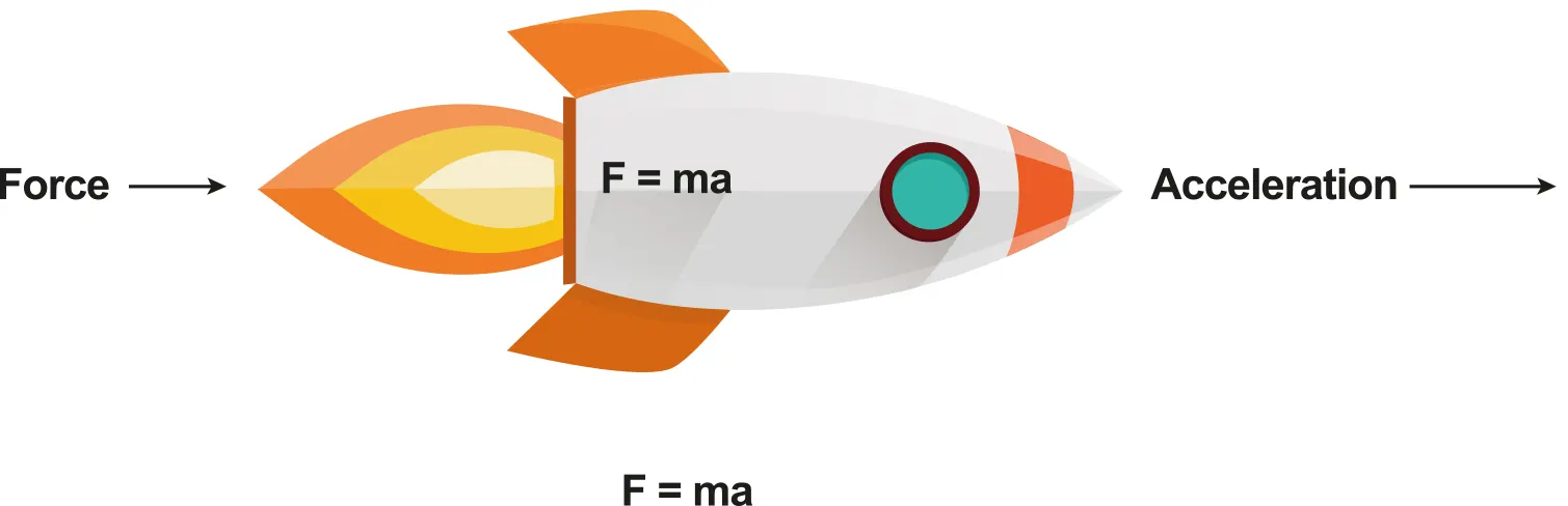
A.2.1-3 Diagram of example of accelerating object
Newton 3rd Law
•
When two bodies A and B interact, the force that A exerts on B is equal and opposite to the force that B exerts on A
•
For every action (forces) on one object, there must be an equal and opposite reaction (forces) on another object
A.2.2 Free body diagram & Force as a vector
•
As Force is a vector quantity, it can be represented by an arrow that gives the both scaled length (magnitude), and the direction of the force (sign)
•
Therefore, vector mathematics must be used to find the resultant force from two or more vectors
•
As every vector can split into its components, force can do it as well
Free-Body Diagram (FBD)
•
Under the complex situation, diagrams that show all the force’s vector arrows can become complicated
•
One way to avoid this problem is to use a Free-Body Diagram to illustrate what is happening
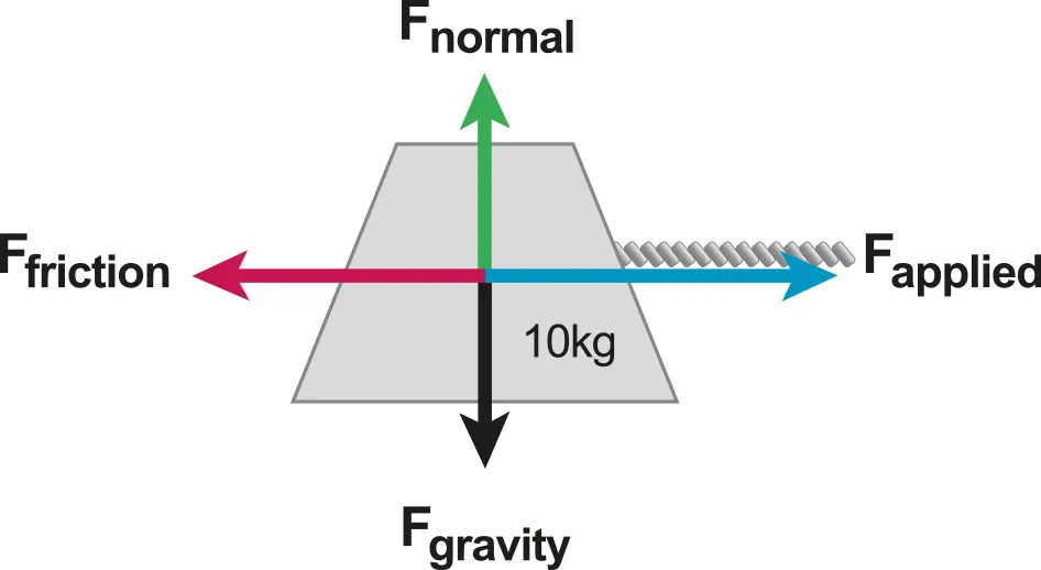
A.2.2-1 Example of Free-body Diagram
Rules for a Free Body Diagram
•
All force vectors are clearly labeled and represented as arrows
•
The force vector arrows’ sizes are proportional to their magnitude, and originate either at the point that represents the center of mass of the body or the point of contact.
•
The diagram is for one body only, each body has an individual FBD
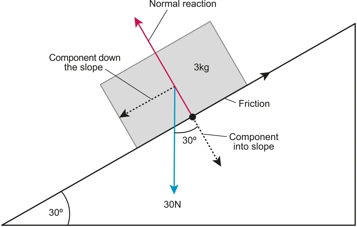
A.2.2-2 Free body diagram of object on an inclined plane
A.2.3 Friction Force
Static and Dynamic Friction
•
Friction is the force that opposes the relative motion of two surfaces
•
It arises because the surfaces involved are not perfectly smooth on the microscopic scale
•
The frictional force that prevents relative motion (v=0) is called static friction
◦
Static friction is a reaction force meaning that it will match the magnitude of any net external force (up to its maximum limit) and be directed in the opposite direction such that the net force is zero. This causes the acceleration to be zero and the object will remain at rest (v=0).
•
Where Static is static friction coefficient and R is the normal reaction force of a body
•
Static friction can have any value up to a maximum value
•
If external force exceeds the maximum static frictional force, the static friction will no longer be able to prevent the motion, and the object will begin to move.
•
The frictional force between two surfaces sliding across one another is called dynamic friction
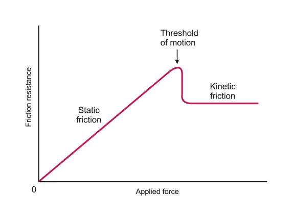
A.2.3-1 Graph representing static and dynamic frictions
•
Formula of Friction is :
•
Where is the dynamic friction coefficient and R is the normal reaction force of a body
•
It should be noticed that the value of dynamic friction is constant as long as the normal reaction force is constant and is always smaller in magnitude than the maximum force of static friction
•
The value of the coefficient of dynamic friction is always smaller than the coefficient of static friction such that
•
If the surfaces are perfectly smooth, then the friction coefficient is 0
•
Friction coefficients depend on BOTH surfaces.
A.2.x Spring force
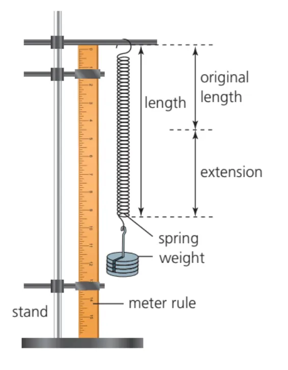
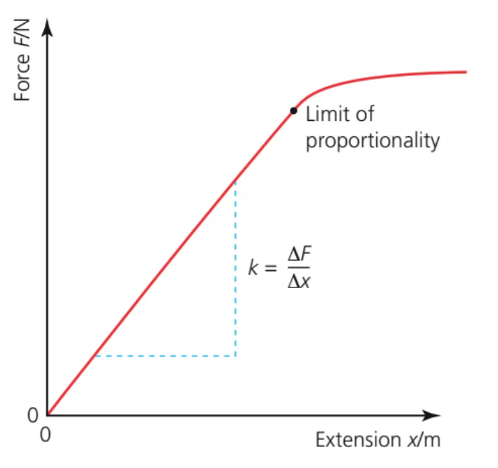
Hooke’s law
•
The forces caused by spring follow two basic rules
◦
The spring force is proportional to the displacement
▪
Larger compression/extension of the spring causes greater forces
◦
The direction of the force is always towards the equilibrium position
▪
Springs always try to return to their original size and position where
•
The equation for the spring force is also referred to as Hooke’s law
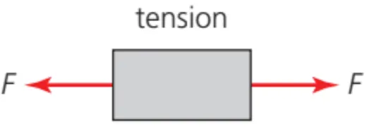
A.2.x Tension force
Tension force
•
Tension forces are caused by ‘pulling’ strings or ropes.
•
Tension forces can only ‘pull’ an object but cannot ‘push’ an object away
•
Pulling a string with a force F causes the same force to be exerted on the object attached on the other end of the string
◦
So in essence strings and ropes are a way to apply forces to any object attached to the other end
•
The force of tension on both sides of the string must be the same
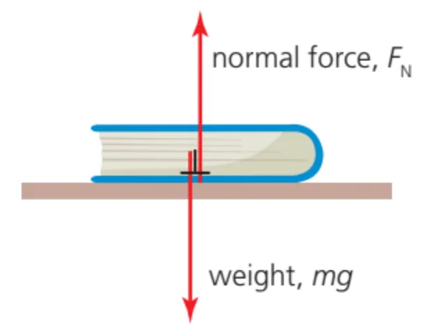
A.2.x Normal reaction force
Normal forces
•
Normal simply means that the force is perpendicular (at a right angle) to the surface.
•
Normal forces cannot move the object to the sides
A.2.x-3
Reaction forces
•
Reaction forces imply that their value can change depending on the other forces applied on the object
•
Since reaction forces can depend on the other forces, there must be a condition (or requirement)
◦
Usually the condition is that
◦
if the object is not moving (or moving at a constant velocity
◦
Otherwise if the object is accelerating
A.2.x Viscous drag
Resistance forces due to drag
•
Resistant forces are always in the opposite direction as the velocity
•
Resistant forces can usually only “slow down” a moving object
◦
Remember that its the relative velocity decreases

Factors affecting drag
•
Velocity,
•
Fluid viscosity
•
Size of the object (radius )
•
•
This assumes that the object does not cause any turbulence in the fluid as it moves, so it generally only applies to low velocities and high viscosities.
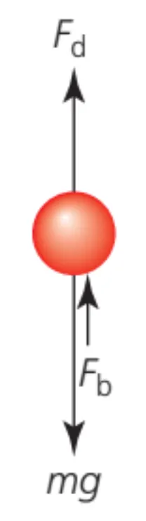
Terminal velocity
•
An object free falling through a liquid will accelerate due to gravity, but as its velocity increases, the force of drag also increases.
•
After a long enough period of time, the force of drag will equal the force of gravity, and since the net force is zero, the object will no longer accelerate.
◦
•
The velocity at which this occurs is referred to as the terminal velocity
A.2.x-5
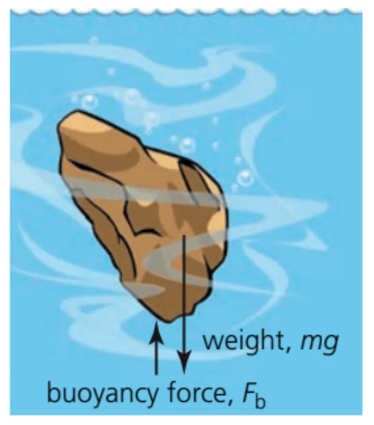
A.2.x Buoyancy
Force of buoyancy
•
Buoyancy is the force acting on a body submerged under a liquid (or fluid)
•
The force of buoyancy is proportional to the weight of the fluid displaced by the object
◦
Weight of the fluid displaced is simply the mass of the fluid that would have occupied the same volume of the object times the gravitational acceleration
◦
Mass of the fluid displaced is calculated using the density of the liquid such that:
▪
◦
•
The force of buoyancy is not the net force so remember that in order to calculate the net force other forces such as the force of gravity must be considered
◦
•
The mass of the object can also be expressed in terms of density. Just remember that the mass of the object depends on the density of the object (not the density of the liquid!)
◦
◦
A.2.x-6
A.2.x Other forces
Forces caused by fields
•
Fields are used to calculate forces by simply multiplying them by some quantity that is the cause of the force
◦
•
Gravitational forces
◦
Gravitational forces are caused by mass so:
◦
Gravitational
◦
•
Electric forces
◦
Electric forces are caused by charges so
◦
◦
•
Magnetic forces
◦
Magnetic forces are caused by moving charges (velocity and charge)
◦
◦
A.2.4 Force and momentum
Momentum
•
Momentum, or linear momentum, is defined as the product of mass and velocity
•
Momentum is a vector quantity, thus has both a magnitude and a direction
•
For example, if an object traveling to the right has a positive momentum, then an object traveling to the left has a negative momentum
•
The SI units of momentum is kgm/s
A.2.4-1 Example Diagram showing the system of momentum
•
The force and momentum equation could be derived from Newton’s 2nd law and the algebraic definition of acceleration :
A.2.5 Impulse
Impulse
•
Impulse is defined as change in an object's momentum, or the integral of a force over the time interval for which it acts
•
A change of momentum implies that the velocity of an object has changed such that:
◦
•
Or that the mass of the object has changed while the velocity is constant such that:
◦
•
Either way, in order for the momentum to change
◦
the velocity of the object must have changed,
▪
it must accelerate have accelerated,
▪
a force must have been exerted on the object
◦
Or the since the mass has changed
▪
A force is required to keep the object moving at the same velocity
•
Another way to derive the force-impulse relationship is to start with the fact that then multiplying both sides by mass yields
◦
◦
But since:
▪
▪
◦
•
As derived above, change in momentum numerically equal to Ft, thus the formula of impulse is therefore
◦
In a full calculus notation :
•
As such, the physics meaning of the area under the F-t curve is impulse
•
Impulse is a vector quantity, possessing a magnitude and a direction
•
The SI unit of impulse is Ns
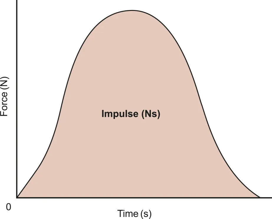
A.2.5-1 Force-time graph representing value of impulse
A.2.6 Conservation of linear momentum
Conversation of Momentum
•
In a closed system, the total momentum remains constant
◦
This could be derived from Newton 2nd and 3rd laws
•
From Newton 2nd Law, we notice that :
•
Likewise from Newton 3rd law :
•
Rearrange the equation :
•
Therefore :
•
Under the condition of mass being constant
A.2.7 Collisions
Collision and Momentum
•
In both collisions and explosions, momentum is always conserved
•
However, kinetic energy might not always be. This could be distinguished by the terms “elastic” and “inelastic”
◦
Elastic - If the kinetic energy is conserved
◦
Inelastic - If the kinetic energy is not conserved
•
Collisions are when objects strike against each other :
•
Elastic collisions are commonly those where objects collide, but none of the kinetic energy is converted to other types of energy during the collision
•
Inelastic collisions are commonly those where objects collide, but some of the kinetic energy is converted into either thermal energy (heat), sound energy, deformation energy, etc
◦
For Inelastic collisions, the total initial momentum and the total final momentum are equal to each other such that:
•
Perfectly inelastic collisions occur when not only does some of the kinetic energy get converted into other types of energy, but the objects stick together after the collision.
◦
Then the final velocity of both objects is the same
◦
The maximum amount of kinetic energy is lost
◦
For Perfectly Inelastic collisions, the initial and final momentums are still equal but there is only one final velocity since the objects are stuck together and move at the same velocity:
•
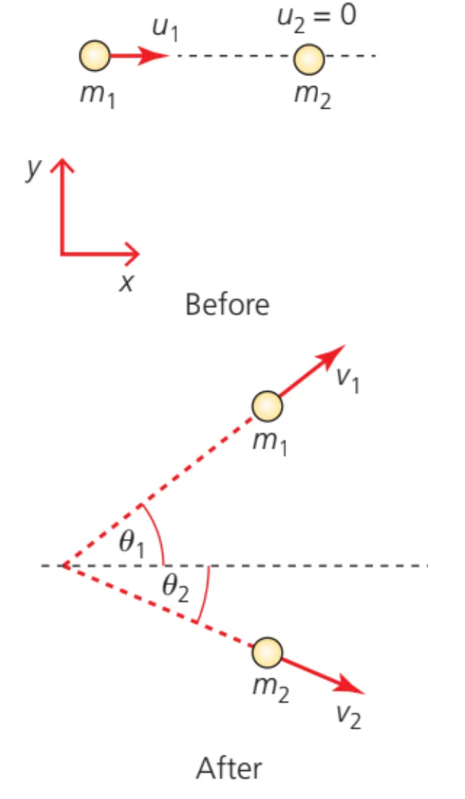
In 2 dimensions, the vertical momentum and horizontal momentum are both conserved and will form 2 equations, and apply to all collisions.
•
In 2 dimensions, the total kinetic energy is only conserved during elastic collisions, and requires only one equation.
◦
Even though the sum of the vertical kinetic energy and the horizontal kinetic energy does add up to the total kinetic energy, they are not calculated separately.
•
Special collision cases:
◦
During one dimensional elastic collisions where both objects have the same mass
▪
so basically the velocities are switched
◦
During two dimensional elastic collisions where both objects have the same mass and one object is at rest
▪
The final velocities of both objects are at a 90 degree angle
A.2.8 Thrust
Rockets
•
The force (thrust) produced by the fuel is equal to the product of the velocity of the exhaust and mass of fuel ejected per second
◦
Propellers, helicopters, and drones
•
The force produced by propellers moving air is also
•
The mass of the air moved is calculated using the definition of air density
◦
•
The volume of the air moving past the propeller is equal to the cross-sectional area of the propeller, , times the distance the air has moved past the propeller, .
◦
•
The distance the air moves past the propeller is simply the product of speed of the air and the change in time
◦
•
Substituting into the original force equation and simplifying yields the force equation:
◦
A.4.1 Period, frequency, angular displacement and angular velocity
Properties of Circular Motion
•
Motion that involves :
◦
Period: Time for one full revolution (or time required to move around the circle once)
◦
Frequency: Number of times the object revolves around the center in one second
◦
Angular displacement: The change in the angle
◦
Angular velocity: Rate of change of the angle
is defined as circular motion
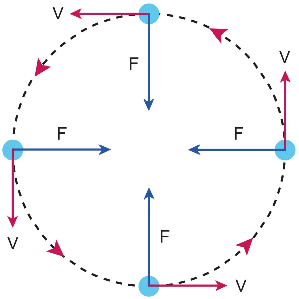
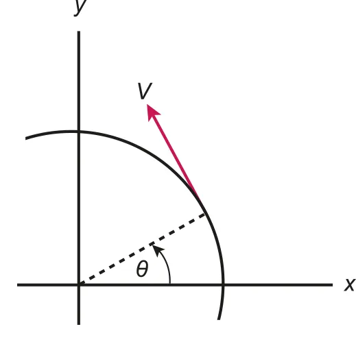
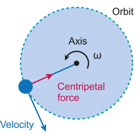
A.4.1-1 Diagram shows the centripetal force with resultant force and circular velocity
Uniform Circular Motion
•
Uniform circular motion refers to circular motion at constant speed
•
Speed remains constant while angular velocity and angular acceleration constantly changes
•
Magnitude of velocity remains constant, yet the direction of velocity constantly changes
◦
Acceleration causes the constant change in direction
•
The acceleration is always directed towards the center of the circular path
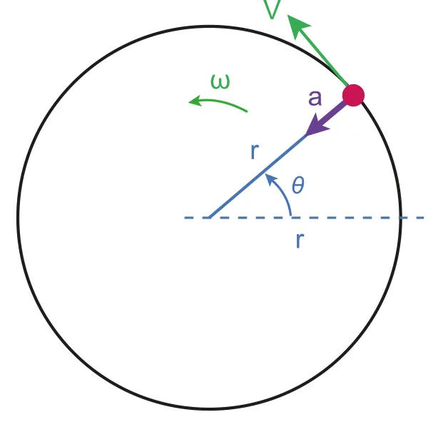
A.4.1-2 Diagram of angular velocity
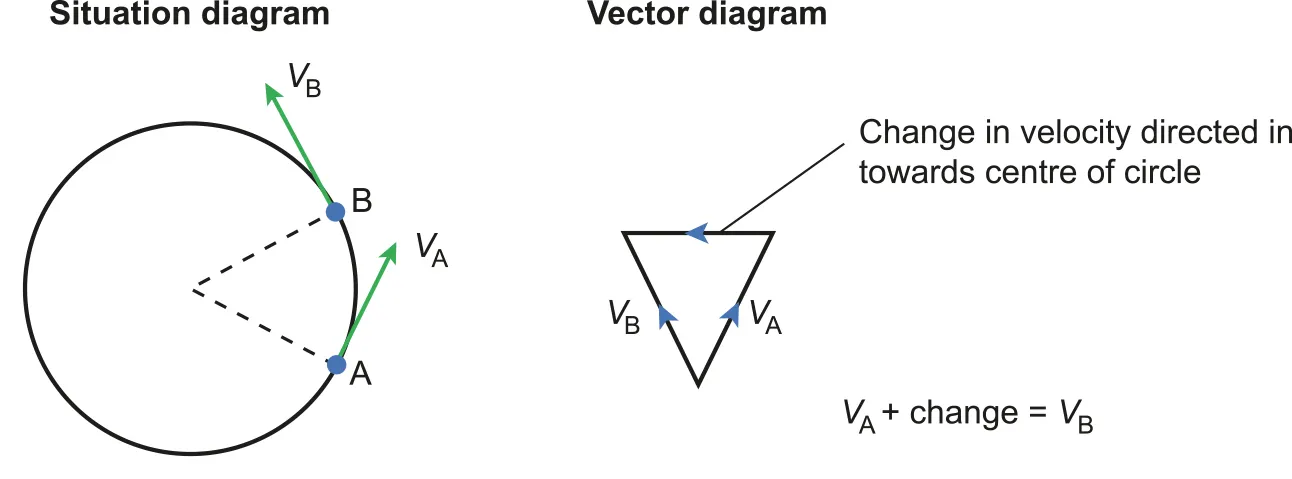
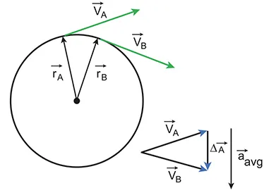
A.4.1-3 Anotated diagram with resultant vectors
•
The diagram implies that the resultant vector of two angular velocity is towards to the centre of circle
◦
change in velocity = acceleration, so acceleration is always towards to the centre of circle
•
Period, : time taken for the object to complete one full circle
•
Frequency, : number of cycles completed in one second
•
Equation that explains the relationship between frequency and period :
Formulas for Uniform Circular Motions
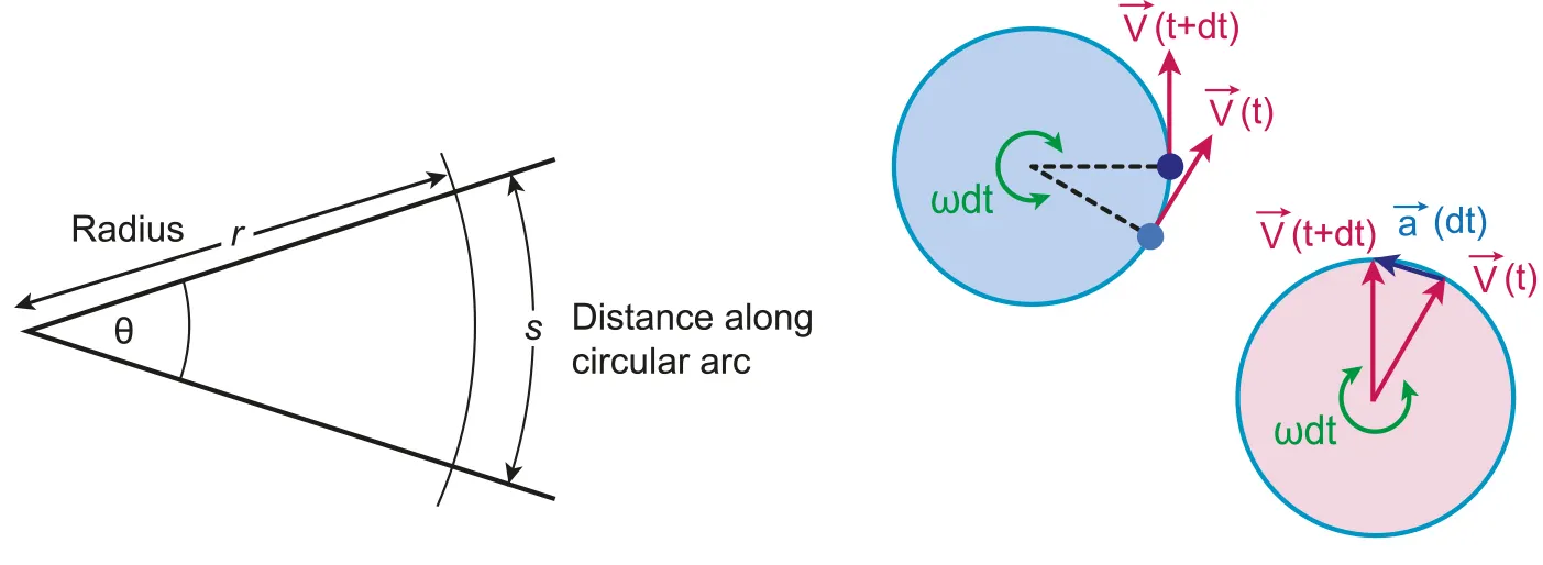
A.4.1-4 Diagram of circular velocity with annotations
A.4.2 Centripetal force
Centripetal Force
•
Centripetal force: the force required (resultant force) to cause the centripetal acceleration
A.4.2-1 Graph showing velocity of object during the circular motion
•
Using the period:
•
Remember that centripetal force is a force requirement! This means that other real forces must add up in a way that it satisfies this requirement
◦
In the direction towards the centre of the circle:
▪
▪
•
A.4.2-2 Diagram of centripetal force is always towards to the centre
Properties of centripetal force
•
Points towards the center of the circle
•
Perpendicular to the instantaneous velocity
•
Work done by centripetal force = 0
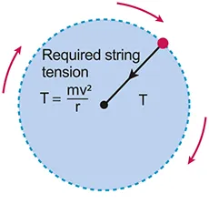
A.4.2-3 Diagram with Tension and Centripetal force
A.4.3 Centripetal acceleration
Centripetal Acceleration
•
acceleration which causes the circular motion
◦
directed towards the center of the circular motion
◦
is perpendicular to the instantaneous velocity of the object
where
A.4.3-1 Diagram showing the resultant vector of velocity of object during circular motion is towards to the centre