

B.5.1 Ohm's Law
Mathematical Approach of Ohm’s Law
•
As mentioned previously, whenever there is a potential difference there must be an electric field
•
When a potential difference is established at the ends of a conductor, an electric field is established within the conductor that forces electrons to move and create the current
•
The size of the current is different in the different conductors, as each conductor will operate with different efficiency
•
The properties of the conductors to resist the current flow is called electric resistance
•
The equation of resistance is :

B.5.1-1 Equations explaining Ohm’s Law with notations
B.5.1-1 Equations explaining Ohm’s Law with notations
•
This relationship, we called it ohm’s law, and the unit is ohm, symbol
•
Materials that obey ohm’s law have a constant resistance in any circumstances
•
For those ohmic materials, a graph of I versus V gives a straight line through the origin

B.5.1-2 Graph of current against voltage in ohmic materials
•
A filament light bulb will obey Ohm’s law as long as the current through it is small
◦
As the current is increased, the temperature of the filament increases and so does the resistance
◦
Diodes and thermistors also deviate from the ohm’s law

B.5.1-3 Graph of current against voltage in filament light bulb
B.5.2 Factors affect the resistance
Factors of Resistance
•
There is some factors that can give influence to the resistance of matter :
•
Nature of the material
•
Length of the wire
•
Cross-sectional area of the wire
•
For most metallic materials, an increase in the temperature results in the increase in resistance :
•
The constant is called resistivity and depends on the materials
Voltage
•
If there is a current through a conductor that has resistance, then there must be potential difference across the ends of that resistor
•
The term Voltage is commonly used for the potential difference at the ends of a resistor :
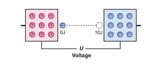
B.5.2-1 Diagram explaining potential difference with charges
B.5.3 Electric Power
Electric Power
•
Power refers to rate of doing work, the power P dissipated in the resistor in moving a charge q across it in time t is :
•
Alternatively :
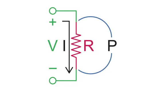
B.5.3-1 Diagram shows the circuit with electric cell
Electromotive force (emf)
•
In a circuit, charges need to be pushed in order to drift in the same direction inside a conductor
•
To do this we need an electric field
•
To have an electric field requires a source to provide potential difference
◦
In a simple circuit, potential difference is usually supplied by a battery, a collection of cells

B.5.3-2
•
EMF is defined as the work done per unit charge in moving charges across the battery terminals
•
Emf is the potential difference across the battery terminals when the battery has no internal resistance
•
Emf is measured in volts
•
When there is no internal resistance, the emf has the equation of :
B.5.4 Kirchoff's Law
Simple Circuits Analysis
•
We have so far defined emf, voltage, resistance, current and power dissipated in a resistor
◦
this means that we are now ready to put all these ideas together to start discussing the main topic of this chapter, electric circuits
•
The mechanism of a circuit is that, as soon as voltage exists, the potential must be used out across the one complete circle around the circuit
•
The potential will be used out or added due to the circuit element
•
Cells will give the potential; resistors will take out the potential

B.5.4-1 Diagram of circuit with resistor
•
As shown in the diagram, when there is negligible internal resistance
◦
all the emf will act as a potential difference across the circuit, so the current could be calculated by using Ohm’s law :
Resistors in Series

B.5.4-2 Part of circuit with resistors in series
•
The potential difference across each of the resistors is :
•
The sum of potential difference is thus :
•
If we were to replace the three resistors by a single resistor of value R1+R2+R3, there is no difference in the result
•
Thus , in series circuit, the resistors are :
Resistors in Parallel

B.5.4-3 Part of circuit with resistor in parallel
•
The current that enters the junction at A must equal the current that leaves the junction at B by the conservation law of charge
•
The left ends of the three resistors are connected at the same point and the same is true for the right ends
•
This means that three resistors have the same potential difference across them
•
This is called a parallel connection
•
Thus :
More complex Circuits
•
A typical circuit will contain both parallel and series connections
•
In this case, you just have to calculate the resistance in the parallel connection then sum up with the series connection
Heating effect equations :
•
We saw earlier that the power P dissipated in a component is related to the potential difference V across the component and the current I in it :
•
The energy E converted in time dt is :
•
When either V or I are unknown, then two more equations become available :
•
Kirchhoff’s first and second laws :

B.5.4-4 Diagram of circuit with various resistors
B.5.5 Electric cells
Electric Cells
•
Electric currents can produce a chemical effect
•
The cells are used until they are exhausted and then thrown away are called primary cells
•
Rechargeable cells are known as secondary cells

B.5.5-1 Symbol of Electric cell
Internal resistance and emf of a cell
•
The materials from which the cells are made have electric resistance in just the same way as the metals in the external circuit
•
This internal resistance has an important effect on the total resistance and current in the circuit

B.5.5-2 Curcuit of showing internal resistance
•
The formula of emf of a cell is given by :
•
Where r is the internal resistance inside of the cell